| Pressure Equalization |
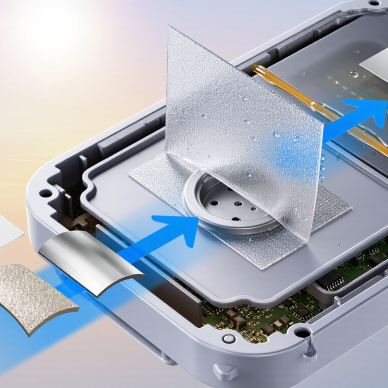
The membrane should allow air exchange while preventing liquid water from passing through. |
Airflow should be specified at a defined pressure differential, commonly reported in L/min at 1 kPa or an equivalent test condition. |
Pressure changes caused by heating, cooling, altitude, or enclosure operation can stress seals and housings. Controlled airflow helps reduce pressure buildup. |
Measure air permeability or airflow using a calibrated pressure-flow test system. Compare results with the enclosure design requirement. |
Critical |
| Water and Liquid Ingress Protection |
Use a microporous, hydrophobic membrane with a water-entry pressure suitable for the enclosure’s exposure level. |
For many outdoor enclosure applications, a water-entry pressure of at least 70 kPa is used as a practical starting point; higher exposure may require more. |
The membrane must resist rain, splashing, condensation, and temporary water contact without blocking normal air exchange. |
Test water-entry pressure and conduct the relevant enclosure ingress test after membrane installation. |
Critical |
| Oil, Fuel, and Chemical Resistance |
Select a membrane structure and adhesive system that are compatible with expected oils, cleaning agents, fuels, coolants, and process chemicals. |
Evaluate the actual chemical list at the expected concentration, temperature, and exposure duration. No universal resistance rating applies to every adhesive membrane. |
Hydrocarbon or solvent exposure can reduce hydrophobicity, swell the adhesive, weaken the bond, or alter airflow performance. |
Perform immersion, splash, or vapor exposure followed by checks for adhesion, water-entry pressure, airflow, and visual damage. |
Critical |
| Air Permeability |
Specify sufficient airflow for pressure equalization without creating an unnecessary pathway for contaminants. |
Common product data may be reported in L/min·cm² or L/min at a stated pressure differential. The selected value should be based on enclosure volume and pressure-change rate. |
Higher airflow can improve pressure response, but performance must be balanced against dust, water, and acoustic requirements. |
Measure airflow at several pressure differentials and confirm stable performance after environmental conditioning. |
High |
| Pore Structure and Particle Barrier |
The membrane should have a controlled microporous structure that provides air passage while limiting liquid and particulate ingress. |
Do not select by nominal pore size alone. Review the pore-size distribution, bubble-point data, membrane thickness, and final water-entry performance. |
Nominal pore size does not fully predict liquid resistance, especially after contamination, flexing, or chemical exposure. |
Review bubble-point or pore-distribution data and test the finished vent assembly under the intended conditions. |
High |
| Adhesive Bond Strength |
The adhesive should bond reliably to the actual enclosure substrate, coating, texture, and surface energy. |
Define minimum peel and shear performance after application and environmental aging. Values must be established for the selected substrate and geometry. |
A strong membrane can still fail if the adhesive lifts, channels, or delaminates from plastic, metal, painted, or powder-coated surfaces. |
Conduct 180-degree peel, static shear, and edge-lift testing on production-representative substrates. |
Critical |
| Application Temperature |
The adhesive should be applied within a controlled temperature and humidity window recommended by the material supplier. |
A common pressure-sensitive adhesive installation range is approximately 15–30°C, unless the qualified product specification permits otherwise. |
Low temperature can reduce wet-out and initial tack, while high humidity, condensation, or contamination can compromise the bond. |
Verify bond formation at the lowest and highest planned installation conditions, including the minimum dwell time before handling. |
High |
| Operating Temperature |
The membrane, support layer, and adhesive should maintain required performance across the complete service temperature range. |
A broadly used evaluation window for industrial enclosures is approximately −40 to +125°C; the actual requirement depends on the application. |
Temperature cycling can cause shrinkage, adhesive creep, embrittlement, loss of tack, or changes in airflow and water resistance. |
Perform thermal aging and temperature cycling, then recheck adhesion, airflow, water-entry pressure, and dimensional stability. |
Critical |
| UV and Weathering Resistance |
For exposed installations, select a membrane and adhesive with documented resistance to ultraviolet radiation, moisture, and outdoor weathering. |
Use an accelerated weathering program appropriate to the application; outdoor exposure should be assessed over the intended service life rather than by a single generic rating. |
UV and weather can embrittle polymer layers, discolor materials, reduce adhesion, and change membrane permeability. |
Use accelerated UV and condensation exposure followed by outdoor correlation where required. |
High |
| Substrate Compatibility |
Confirm adhesion to the actual substrate, including molded plastics, aluminum, stainless steel, coated metals, and textured surfaces. |
Assess surface energy, roughness, curvature, release-agent residue, paint chemistry, and coating adhesion before final selection. |
The same adhesive may perform differently on low-surface-energy plastics, powder coatings, anodized metal, or contaminated surfaces. |
Use production-equivalent panels and test initial adhesion, aged adhesion, and failure mode after cleaning and environmental conditioning. |
Critical |
| Contamination and Dust Resistance |
The vent should preserve airflow and water resistance after exposure to dust, fibers, and installation debris. |
Define a particle challenge representative of the application. Performance should be measured before and after contamination, not inferred from pore size alone. |
Blocked pores can reduce pressure equalization and increase enclosure pressure stress. |
Expose the vent to representative dust, then measure airflow, water-entry pressure, and visible blockage. |
High |
| Condensation and Humidity Performance |
The membrane should remain breathable and bonded after repeated high-humidity exposure and condensation cycles. |
Evaluate at high relative humidity, including repeated cycling between cold and warm conditions; use the actual enclosure thermal profile where possible. |
Condensation can challenge hydrophobicity, promote adhesive edge lift, and cause corrosion if pressure equalization is inadequate. |
Run humidity cycling and condensation testing, followed by visual inspection and functional performance tests. |
High |
| Mechanical Durability |
The membrane and adhesive should resist vibration, shock, flexing, abrasion, and handling damage. |
Test levels should reflect the equipment category and mounting location. Evaluate both the membrane center and the adhesive perimeter. |
Mechanical damage may create leakage paths or cause gradual delamination during service. |
Conduct vibration, shock, flex, and abrasion tests as applicable, then repeat ingress and airflow measurements. |
High |
| Vent Geometry and Effective Area |
Choose the vent diameter, shape, and effective open area based on the enclosure volume, pressure-change rate, and available mounting space. |
Use airflow calculations or testing to determine the required vent area. A larger geometric area does not always equal a larger effective airflow area. |
Insufficient area can cause slow pressure equalization, while excessive area may reduce available protection or create packaging conflicts. |
Measure pressure response on a representative enclosure using the selected vent size and installation position. |
Critical |
| Adhesive Coverage and Seal Design |
The adhesive should provide a continuous seal around the vent opening without covering the active membrane area. |
Define the minimum bond width, edge clearance, corner radius, and allowable wrinkles or channels in the assembly drawing. |
Gaps or adhesive contamination over the active area can create leakage or restrict pressure equalization. |
Inspect the bond line visually and with leak or ingress testing after installation and environmental aging. |
Critical |
| Manufacturing and Installation Control |
The vent should be compatible with manual, semi-automatic, or automated application processes. |
Define liner release force, placement tolerance, application pressure, dwell time, storage conditions, and allowable rework. |
Consistent installation is essential because surface preparation and placement quality strongly affect adhesive performance. |
Validate the complete assembly process using capability studies, visual standards, and destructive bond audits. |
High |
| Storage and Shelf Life |
Packaging should protect the adhesive and membrane from humidity, contamination, pressure, and excessive temperature. |
Use the supplier’s documented shelf-life and storage limits; a controlled indoor storage condition near 20–25°C and moderate humidity is commonly preferred. |
Improper storage can change liner release, adhesive tack, membrane moisture content, and application performance. |
Test material at the beginning and end of the stated shelf life, including adhesion and functional vent performance. |
Medium |
| Regulatory and Material Documentation |
Require complete technical documentation for the membrane, adhesive, liner, and any backing or support layer. |
Review safety data, restricted-substance declarations, relevant material compliance statements, and traceability records required for the destination market. |
Documentation supports qualification, change control, customer audits, and regulatory compliance. |
Audit technical files, certificates, change-notification procedures, and batch traceability before approval. |
High |