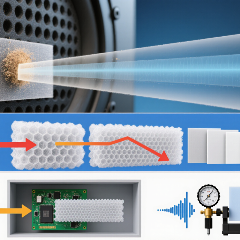
| Acoustic transmission loss |
Protective membranes should preserve the output of microphones, speakers, buzzers, and pressure-sensitive acoustic sensors. |
Aim for no more than 1–2 dB attenuation across the critical operating band, such as 300 Hz–10 kHz, unless the product has a different acoustic bandwidth. |
Measure the complete housing and membrane assembly using a calibrated acoustic test fixture. Compare sound-pressure level with and without the membrane. |
Use a thin, acoustically open membrane with uniform pore structure. The housing opening, adhesive, mesh, and grille often affect sound more than the membrane alone. |
| Acoustic frequency range |
Different applications require different acoustic transparency. Human speech, alarms, ultrasonic sensors, and audio devices do not use the same frequency range. |
Define the passband before choosing the membrane; common starting ranges are 300 Hz–3.4 kHz for voice and 100 Hz–10 kHz for wider-band audio. |
Perform frequency-response testing over the required band at the intended sound-pressure level. |
Select the membrane and opening geometry as a system. A small or tortuous acoustic path can create resonances or high-frequency roll-off. |
| Air permeability |
Air permeability supports acoustic coupling and pressure equalization, but excessive airflow can reduce liquid resistance and allow contaminants to move through the vent path. |
Use the lowest airflow resistance that meets the acoustic requirement. Establish a project-specific acceptance limit rather than relying on a universal value. |
Measure airflow rate versus pressure differential using a controlled flow bench. Record test area, temperature, humidity, and pressure range. |
Compare candidate membranes using the same exposed area and mounting construction. Air-permeability values are not directly comparable when test methods differ. |
| Pressure equalization |
Temperature and altitude changes can create pressure differences that stress seals, distort housings, or cause pumping of moisture through the enclosure. |
Define the required pressure-equalization time and maximum internal pressure differential. A practical starting requirement is stable equalization without compromising the liquid barrier. |
Apply controlled positive and negative pressure cycles and record equalization time, leakage, and housing deformation. |
Increase vent area or use a lower-resistance membrane when pressure response is too slow, while checking the impact on water and dust protection. |
| Water-entry resistance |
The membrane must block rain, splash, condensation, and temporary immersion while remaining acoustically functional. |
For products requiring IP67-level protection, the completed enclosure should withstand temporary immersion up to 1 m for 30 minutes. Higher pressures require a separately validated design. |
Test the complete product enclosure according to the applicable IP rating procedure, followed by acoustic and functional checks. |
Do not use membrane water-entry pressure as a substitute for the finished-product IP test. Bond-line defects and housing tolerances are common failure points. |
| Dust and particle protection |
Dust can block the acoustic path, contaminate the transducer, and reduce long-term airflow or sensitivity. |
For dust-tight designs, specify an enclosure-level IP6X requirement and define the particle environment, including dust type and exposure duration. |
Conduct the applicable dust-ingress test on the finished enclosure and inspect the membrane, adhesive edge, and acoustic cavity. |
Choose a membrane with suitable pore structure and protect the perimeter from bypass leakage. A membrane cannot compensate for an unsealed housing joint. |
| Liquid surface tension and contaminants |
Detergents, oils, surfactants, and low-surface-tension liquids can penetrate a membrane more easily than clean water. |
Define exposure to water, salt solution, detergents, oils, fuels, and cleaning agents. Specify the required liquid-entry resistance after chemical exposure. |
Expose the assembled vent to representative liquids, then repeat liquid-entry, airflow, and acoustic tests. |
Use application-specific chemical screening. A membrane that resists water may not provide the same protection against surfactant-containing liquids. |
| Operating temperature |
Temperature affects polymer behavior, adhesive performance, housing expansion, and the stability of the seal around the membrane. |
Define the actual operating and storage range. A common electronics design envelope is approximately −40 °C to +85 °C, with higher-temperature requirements validated separately. |
Perform thermal cycling, dwell testing at temperature extremes, and post-test acoustic, airflow, and liquid-entry measurements. |
Rate the membrane, adhesive, carrier, and housing together. The adhesive or carrier may become the limiting component rather than the ePTFE film. |
| Humidity and condensation |
High humidity and condensation can alter acoustic response and create corrosion or electrical leakage inside the enclosure. |
Define high-humidity exposure, condensation cycles, and recovery requirements. For general outdoor electronics, 85% relative humidity testing is commonly used as a screening condition. |
Use temperature-humidity cycling or steady-state damp-heat testing, followed by insulation, acoustic, airflow, and visual inspection. |
Provide a drainage path or suitable vent orientation where condensation is possible. Avoid designs that trap water directly against the acoustic opening. |
| UV and weathering resistance |
Outdoor exposure can embrittle carriers, degrade adhesives, discolor protective layers, and reduce long-term sealing reliability. |
Define sunlight exposure, outdoor service duration, temperature, and any required color or mechanical retention limits. |
Use accelerated UV and weathering exposure appropriate to the application, followed by mechanical, acoustic, airflow, and water-entry testing. |
Protect the membrane perimeter and adhesive from direct UV where necessary. Validate the complete vent construction, not just the raw membrane. |
| Chemical compatibility |
Although ePTFE has broad chemical resistance, nearby adhesives, carriers, coatings, and housing materials may swell, soften, or lose adhesion. |
Screen all expected chemicals, including cleaning fluids, skin oils, plasticizers, fuels, coolants, and salt spray. |
Conduct immersion, wipe, vapor, or splash testing as appropriate, then measure mass, dimensions, adhesion, airflow, acoustic response, and liquid-entry resistance. |
Approve the entire laminate and bonding system. Do not qualify the ePTFE layer independently if it is permanently attached to another material. |
| Mechanical vibration and shock |
Vehicle, industrial, and portable products can experience vibration, impact, acoustic excitation, and repeated pressure pulses. |
Define the product-specific vibration spectrum, shock level, duration, and number of cycles. Include transportation and installation loads where relevant. |
Test the assembled product or representative housing, then check for delamination, tearing, wrinkles, leakage, airflow change, and acoustic drift. |
Use sufficient support around the membrane and avoid sharp edges. The bond perimeter should be designed for the expected strain and thermal movement. |
| Membrane thickness and acoustic mass |
Thicker or multilayer constructions can improve handling and durability but may increase acoustic impedance and reduce high-frequency transparency. |
Choose the thinnest construction that meets handling, pressure, and environmental requirements. Record nominal thickness and allowable variation. |
Measure thickness at multiple locations and correlate it with frequency response, airflow resistance, and water-entry performance. |
Do not select thickness based only on liquid resistance. Opening diameter, membrane tension, support structure, and mounting method also influence acoustic behavior. |
| Effective vent area |
The usable open area determines airflow, pressure response, and acoustic impedance. Adhesive overlap can substantially reduce the active area. |
Specify the minimum effective open area after assembly, not only the nominal cut-out size. Include an allowance for tolerances and partial obstruction. |
Measure the assembled vent geometry and verify airflow and acoustic response across production tolerances. |
Keep the acoustic path short and unobstructed. Avoid excessive adhesive squeeze-out, protective films, narrow slots, and abrupt cavity changes. |
| Adhesive and perimeter seal |
Water and dust frequently bypass the membrane through an incomplete bond, contamination, wrinkles, or insufficient compression. |
Define continuous bond coverage, minimum peel or shear strength, allowable wrinkles, and acceptable edge gaps. |
Use visual inspection, peel or shear testing, pressure decay, liquid-entry testing, and cross-section analysis during qualification. |
Match adhesive chemistry and surface treatment to the housing material. Control cleanliness, pressure, cure time, and storage conditions. |
| Manufacturing tolerances and inspection |
Variation in pore structure, thickness, cut dimensions, adhesive coverage, and placement can cause inconsistent acoustic and environmental performance. |
Define critical-to-quality characteristics, sampling plans, traceability, and maximum allowable variation for each production lot. |
Combine incoming-material inspection with in-process visual checks and periodic airflow, acoustic, and liquid-entry audits. |
Use a production test that correlates with final performance, such as airflow or pressure-decay testing, while confirming correlation through validation. |
| Regulatory and material compliance |
Restricted substances and chemical disclosure requirements may apply to the membrane, adhesive, carrier, ink, and packaging. |
Define applicable requirements such as RoHS, REACH substance communication, halogen restrictions, and product-specific safety rules. |
Review controlled material declarations and perform independent laboratory testing when risk or regulation requires it. |
Qualify the complete material stack and control formulation changes through formal change notification and requalification procedures. |
| Service life and reliability |
Acoustic performance and environmental sealing can drift over time because of contamination, fatigue, adhesive aging, or repeated thermal and pressure cycling. |
Define the intended service life, duty cycle, storage period, and acceptable changes in acoustic response, airflow, and liquid-entry resistance. |
Use accelerated life testing that combines temperature, humidity, pressure cycling, vibration, chemical exposure, and acoustic monitoring where applicable. |
Base the final selection on post-aging performance rather than initial test results alone. Set clear end-of-life criteria before qualification. |